
Samsung CLP-365w Drum Unit Reset — what it is and how it works
Samsung CLP-365w Drum Unit Reset is the process of clearing the imaging unit’s page “odometer” so your printer can resume printing after it shows Replace/Prepare new imaging unit. The CLP-365w (and other models using the CLT-R406 imaging unit) tracks pages with a tiny fuse/“blow” circuit on the drum module. From the factory, the circuit presents low resistance; at first power-up, the printer detects that low value, resets the drum counter, and then blows the little fuse so it only “sees” a high resistance from that point forward and keeps counting. When the counter reaches its limit, printing stops even if the drum still looks fine. Resetting simply means recreating that new-unit low-resistance condition once—safely—so the printer clears the counter.
Samsung CLP-365w Drum Unit Reset — your practical options
Samsung CLP-365w Drum Unit Reset can be done in three main ways:
-
Install a new CLT-R406 imaging unit (zero risk, highest cost).
-
Use a commercial “reset chip/fuse” kit (easy, mid cost).
-
DIY fuse method using a small resistor to simulate a new drum (cheapest if you’re handy).
If your prints were still sharp before the warning, a reset is reasonable. If you see repeating marks, haze, or scratches, replace the imaging unit instead—resetting won’t fix worn hardware.
Samsung CLP-365w Drum Unit Reset — DIY fuse method (56 Ω)
Safety first: Power off and unplug the printer. Work on a clean, static-safe surface. Do not force plastic tabs; avoid touching the green drum surface.
Tools you need
-
Small Phillips screwdriver and flat plastic pry tool
-
56 Ω resistor (¼ W carbon film works well) — some users report 47 Ω also works, but 56 Ω is the common value
-
Optional: fine needle-nose pliers, a tiny bit of tape to hold the resistor legs in place
-
Lint-free cloth for handling

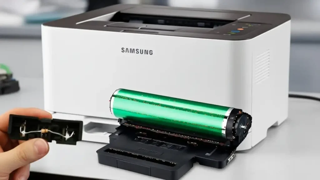
Locate the fuse housing
-
Open the front cover, remove the color toners, and slide out the CLT-R406 imaging unit (it sits beneath the toners).
-
On the front of the imaging unit you’ll find a small black plastic module with two copper pads/terminals—this is the removable fuse housing.
-
Gently pry the housing out. Inside you’ll see a 200 kΩ resistor (always present) and, on some units, a tiny blown fusible resistor that originally provided the low resistance when new.
Install the 56 Ω “fuse” resistor
-
Cut/shape the legs of your 56 Ω resistor so they contact the two pads in parallel with the existing 200 kΩ resistor (you’re recreating the “low resistance” that signals a new drum).
-
For a clean job, you can lightly twist the legs around the posts or pads so they make firm contact. Soldering is optional; a snug mechanical fit is usually enough for the brief detection event.
-
Ensure nothing shorts to surrounding plastic or metal. Keep the resistor clear of the green drum surface.
Power-up reset and verification
-
Reinsert the fuse housing into the imaging unit and reinstall the imaging unit in the printer.
-
Close all covers, plug the printer in, and power on. On first power-up, the printer will read the low resistance, reset the drum counter, and—in designs that blow a fusible link—treat the low-value part as a one-time fuse.
-
After the initialization completes, the red light should go out. Print a Supplies/Configuration report to confirm the imaging unit is reported as new/OK.
-
Power off, open the printer, and remove or leave the resistor in place depending on your preference:
-
One-time reset (recommended): Remove the add-on resistor so the circuit now presents high resistance again (normal run state).
-
Leave-in: Some users leave a standard resistor installed. It normally doesn’t heat under idle detection, but the conservative approach is to remove it after the reset.
Troubleshooting after the reset
LED still red after power-up
-
Reseat the fuse housing and verify your 56 Ω makes solid contact across the two terminals.
-
Inspect for bent tabs or misalignment when reinserting the imaging unit.
-
Power-cycle once and try again.
Resets every power-on (rare)
-
If you permanently solder a low-value resistor, the printer may attempt to treat every boot as a new drum. Remove the resistor after a successful reset so the circuit presents high resistance in normal use.
Print quality is poor even after reset
-
The reset only clears the counter. If you see repeating smudges, scratches, or background haze, the drum may truly be worn—replace the CLT-R406.
I don’t see the tiny “blown fuse” in my housing
-
Many later units ship with only the 200 kΩ present, relying on the printer to blow an external low-ohm element the first time it’s detected. Your add-on 56 Ω supplies the same “new drum” signal for the reset.
I’d rather not DIY
-
Commercial reset kits are essentially a low-ohm element pre-mounted for drop-in use. They cost more than a loose resistor but are quick and tidy.

Care tips and when to replace the imaging unit
-
Keep the printer in a clean, dry environment. Dust accelerates wear.
-
Avoid touching the green drum; fingerprints can mark prints.
-
When repeating defects match the drum circumference, no reset can help—install a new imaging unit.
-
If you frequently hit the drum limit but quality is still good, note your average page volume and budget for either a reset kit or a replacement drum each cycle.