

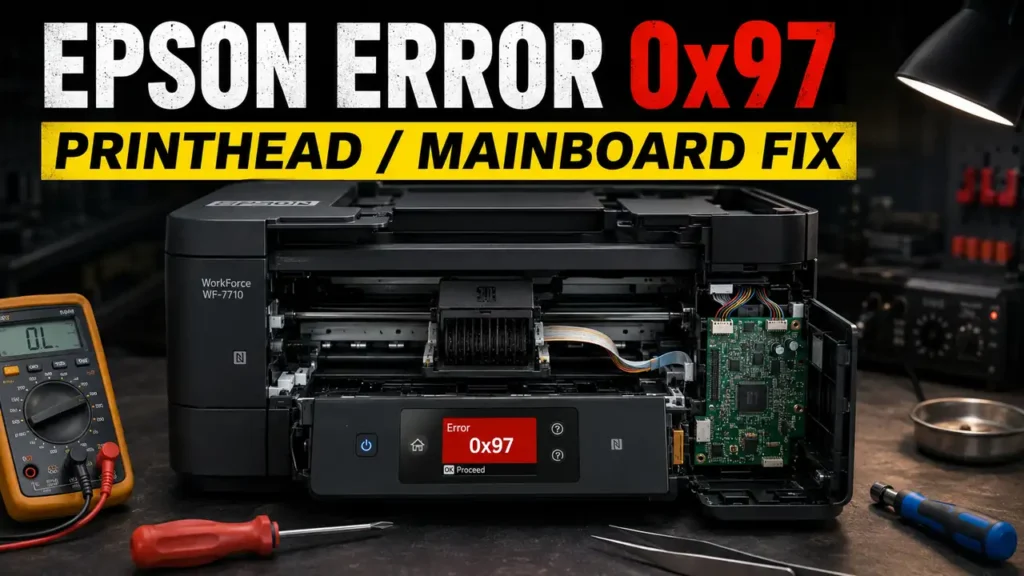
An Epson Error 0x97 Fix is one of the most mechanically intensive diagnostic procedures within the inkjet printer repair community.
When Epson WorkForce models abruptly halt and display this alphanumeric code, the printer is typically experiencing a critical hardware failure related to the motherboard or the printhead’s internal power supply.
While standard user manuals often suggest turning the printer off and contacting support, independent technicians rely on physical isolation methods to trace the electrical fault.
By systematically discharging the mainboard, decontaminating the printhead ribbon cables, and assessing the surface-mount fuses, technicians can determine if the hardware is salvageable.
This technical manual details a hands-on diagnostic approach for an Epson Error 0x97 Fix, including capacitive discharging, mechanical unjamming, and motherboard evaluation.
Safety Warning and Official Stance: Epson’s public support guidance generally directs users to search the exact error code under the specific product’s FAQ/support page or contact service for unresolved printer errors. The hardware teardown described below involves handling components that retain electrical charge and may expose you to liquid ink. This guide is intended strictly for educational and troubleshooting purposes. Proceed at your own risk.
Before You Start: Essential Expectations
To align with professional diagnostic standards, please review the following limitations before attempting this procedure:
-
Unofficial workaround: This is a community-reported diagnostic method, not a guaranteed manufacturer repair protocol.
-
Electrical hazard: Ensure the printer is completely unplugged from the wall outlet before touching any internal ribbon cables or circuit boards.
-
Contamination risk: Moving the printhead manually may expose your hands to residual ink. Polyurethane gloves are highly recommended.
-
Variable success rates: Success is not guaranteed. If the motherboard has sustained a catastrophic short, this isolation protocol will confirm the fault but cannot reverse the physical damage.
Supported Printer Architectures
This hardware diagnostic method has been commonly reported by repair communities across several Epson WorkForce families that utilize high-density PrecisionCore printheads (model-dependent).
| Printer Series | Notable Models (Community Reported) | Primary Component Evaluated |
| Epson WorkForce Pro | WF-3620, WF-3640, WF-4630 | PrecisionCore Printhead |
| Epson WorkForce | WF-7610, WF-7620, WF-7720 | Printhead Ribbon Cables |
| Epson WorkForce | WF-7110, WF-7210, WF-4640 | Main Logic Board (F1/F2 Fuse) |
Diagnosing the Hardware Panic
The Epson printhead utilizes piezo-electric technology, which requires specific voltage pulses to physically push ink droplets onto the page.
If liquid ink accidentally leaks onto the delicate ribbon cables connecting the printhead to the logic board, it may create a short circuit.
In some board-level repair cases, technicians report that a failed F1/F2 surface-mount fuse may accompany printhead or carriage-related shorts.
However, the exact failure path varies by model and should be confirmed with the service manual. Understanding these potential electrical paths is crucial before executing an Epson Error 0x97 Fix.
Phase 1: Deep Capacitive Discharge
Before opening the printer chassis, you must attempt a deep power cycle to clear any transient electrical anomalies. This is the first standard phase of an Epson Error 0x97 Fix.
-
Power down the printer using the main control panel button.
-
Disconnect the AC power cord entirely from the wall receptacle and the back of the printer.
-
Disconnect any USB or Ethernet cables to isolate the machine from external data sources.
-
While the printer is completely unplugged, press and hold the physical Power button for 60 seconds. This may help discharge residual power from the low-voltage rails.
-
Allow the printer to sit idle for at least 30 minutes.
-
Reconnect the AC power cord directly to a dedicated wall outlet (bypassing surge strips) and power on.
If the printer initializes normally, the error was likely a transient voltage spike. If the 0x97 code immediately returns, a physical hardware fault is strongly indicated.
Phase 2: Mechanical Carriage Unjamming
If the deep discharge fails, the logic board may be detecting a physical bind in the printhead carriage pathway.
-
Verify the printer is completely powered off and unplugged.
-
Open the main top scanner unit to expose the internal print zone.
-
Examine the printhead carriage. It is typically locked in the far-right home station.
-
Gently attempt to slide the carriage to the left. If it is locked, locate the small white plastic locking gear mechanism on the left side of the carriage and gently rotate it to release the physical lock.
-
Once freed, glide the carriage back and forth across the metal rail.
-
Use a flashlight to inspect the internal cavity for jammed paper fragments, heavy dust accumulation, or dislodged encoder strips that could be restricting motor movement.
Phase 3: Printhead Contact Decontamination
If the carriage moves freely, the fault may involve liquid ink shorting the data connections. Decontamination is a critical step in the Epson Error 0x97 Fix process.
-
Move the unlocked printhead carriage to the center of the printer for easy access.
-
Remove all ink cartridges and place them safely on a silicone mat.
-
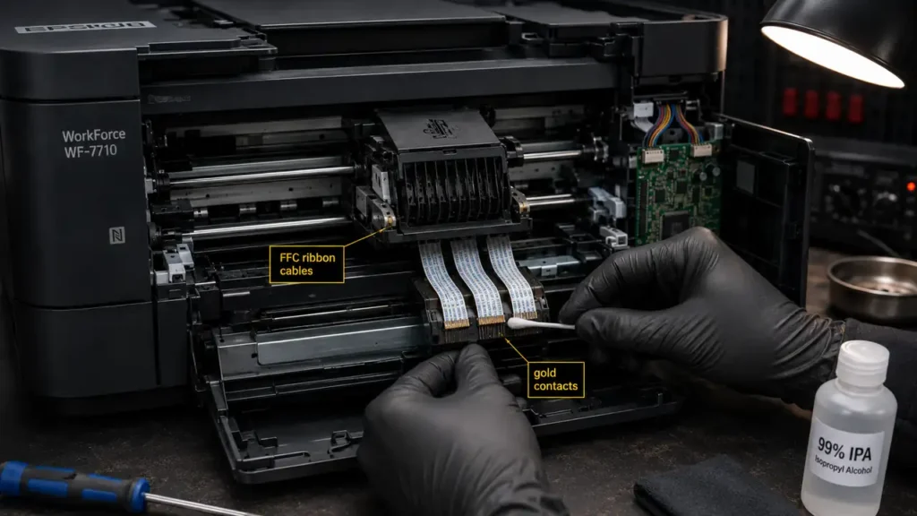
Carefully inspect the Flat Flexible Cables (FFC) connecting the top of the printhead to the carriage board.
-
If you observe wet ink pooling around the gold contact pins of these cables, a short circuit has likely occurred.
-
Lightly saturate a lint-free cleanroom swab with 99% Isopropyl Alcohol (IPA).
-
Gently clean the exposed contacts and the surrounding plastic housing to remove conductive ink residue. Allow a full 15 minutes for complete evaporation before reassembling.
Phase 4: Motherboard F1 Fuse Assessment
If cleaning the contacts does not resolve the issue, the logic board has likely sustained secondary damage. This advanced phase of the Epson Error 0x97 Fix requires isolating the motherboard.
Note: This phase is for board-level technicians only and should not be attempted without the service manual and proper ESD precautions.
-
Accessing the main logic board requires removing the side panels of the printer (refer to your specific model’s service manual for screw locations).
-
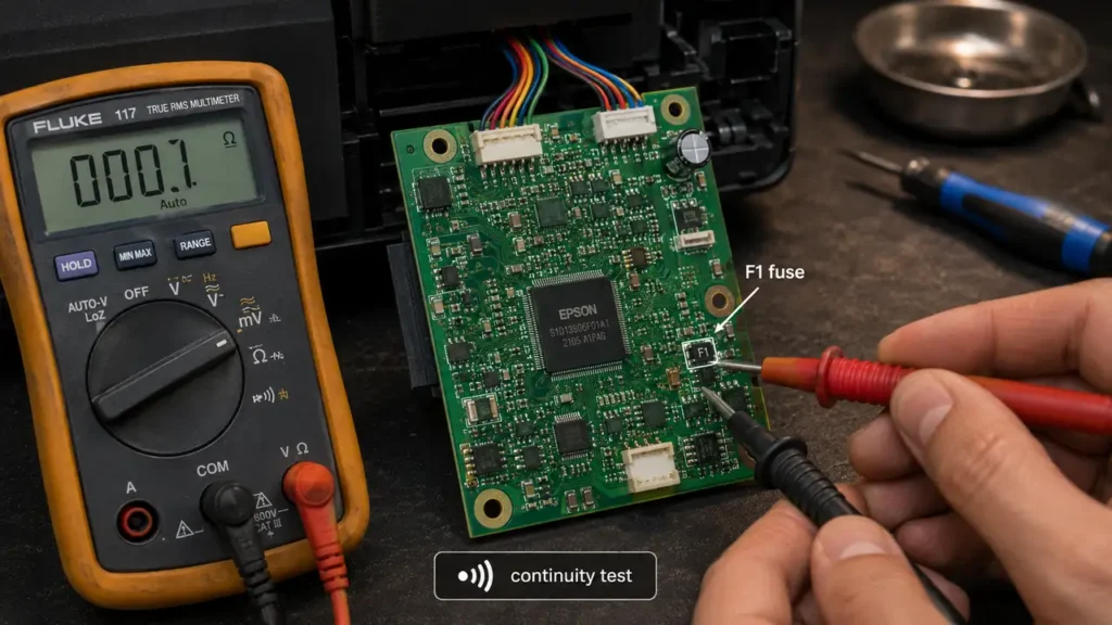
Once the logic board is exposed, use a magnifying glass to locate the surface-mount fuses, typically labeled F1, F2, or F3.
-
Using a digital multimeter set to the Continuity (Ohms) setting, probe both sides of the F1 fuse.
-
A healthy fuse will emit a continuous beep (or display near-zero resistance).
-
If the multimeter displays “OL” (Open Loop) and does not beep, the fuse has blown.
This confirms the motherboard has cut power. In this scenario, resolving the error requires micro-soldering a replacement SMD fuse or replacing the entire logic board.