

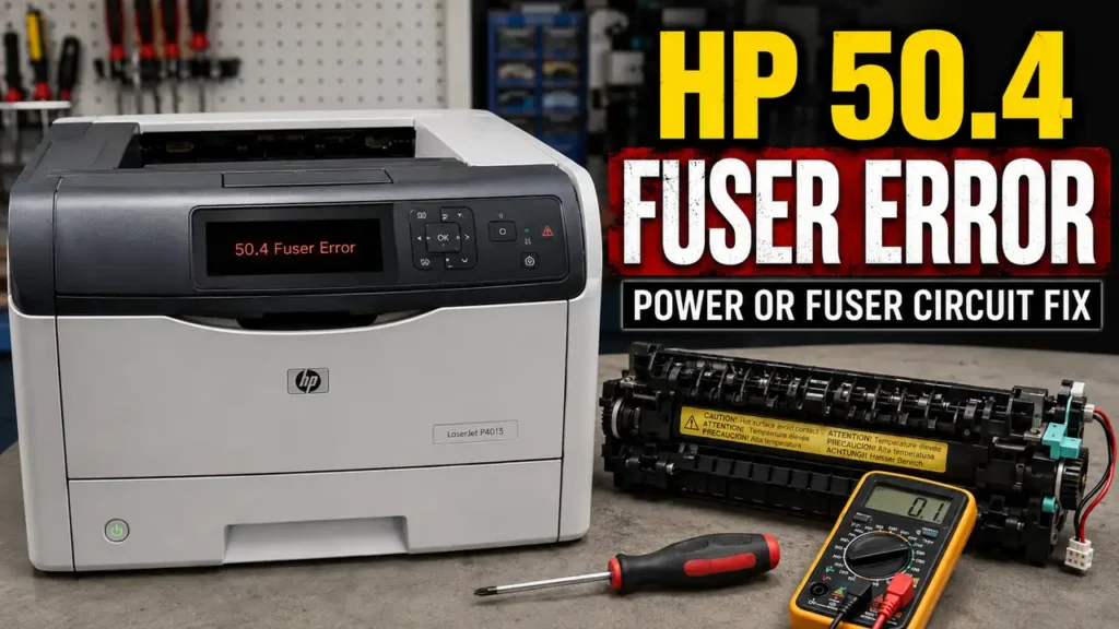
An HP 50.4 Fuser Error Fix is a highly sought-after diagnostic procedure within the laser printer maintenance community.
When HP LaserJet Pro or Enterprise models halt and display this specific 50.4 code, the machine is detecting a critical failure in the line voltage or the fuser’s power delivery circuit.
This is an immediate thermal failsafe. The Engine Control Board (ECB) cuts all power to the fuser to prevent fire hazards or catastrophic damage to the ceramic heating elements.
While many standard IT guides suggest immediately replacing the entire fuser maintenance kit, independent technicians recognize that this error can often be triggered by external power grid fluctuations or a localized thermistor fault.
By systematically evaluating the power source and measuring the fuser’s internal continuity, it is often possible to isolate the exact point of failure before investing in expensive replacement parts.
This technical manual details a hands-on diagnostic approach, including line voltage isolation, fuser extraction, and multimeter continuity testing.
Safety Warning and Official Stance: According to HP, fuser errors indicate a critical hardware fault requiring the printer to be powered down and serviced by authorized personnel. The fuser operates at extreme temperatures (exceeding 200°C) and utilizes high-voltage AC mains. This guide is compiled from independent diagnostic practices and is intended strictly for out-of-warranty educational purposes. Proceed at your own risk. Always disconnect AC power and allow the printer to cool for 45 minutes before handling internal components.
Before You Start: Essential Expectations
To align with best diagnostic practices, please review the following limitations before attempting this procedure:
-
Unofficial diagnostic: This is a community-reported evaluation method, not a manufacturer-approved repair protocol.
-
Hardware tools required: A digital multimeter with continuity and Ohms (Ω) settings is mandatory for Phase 3 of this guide.
-
Thermal hazard: The fuser unit retains severe heat long after the printer is powered off. Adequate cooling time is non-negotiable.
-
Variable outcomes: If the fuser’s ceramic heater is fractured, this diagnostic will confirm the death of the unit; it will not repair physical ceramic damage.
Supported Printer Architectures
This diagnostic evaluation has been commonly reported by repair communities across several HP LaserJet families that utilize instant-on ceramic fuser technology.
| Printer Series | Notable Models (Community Reported) | Component Evaluated |
| HP LaserJet Pro 400 | M401, M402, M425 | RM1-8808 / RM2-5399 Fuser |
| HP LaserJet Enterprise | M506, M602, M605, M608 | RM2-5679 / RM1-8395 Fuser |
| HP LaserJet P Series | P2035, P2055, P3015 | RM1-6405 / RM1-6274 Fuser |
| HP Color LaserJet | M452, M477, CP2025 | RM2-6418 Fuser Assembly |
Diagnosing the Thermal Power Delivery
HP’s instant-on fuser technology utilizes a fragile ceramic heating element coupled with highly sensitive thermistors (temperature sensors).
To rapidly reach the 200°C required to melt toner into paper, the Engine Control Board (ECB) drives high-voltage AC power directly into the fuser using an electronic component called a Triac.
The logic board continuously monitors the frequency (50Hz/60Hz) and the voltage of the incoming AC power.
If the voltage drops unexpectedly, or if the AC sine wave is distorted, the logic board cannot safely regulate the Triac.
To prevent the ceramic heater from going into thermal runaway, the motherboard triggers the 50.4 Error, indicating a line voltage abnormality or a dead circuit.
Phase 1: Line Voltage and UPS Isolation
Before opening the printer to attempt an HP 50.4 Fuser Error Fix, you must completely rule out external power delivery issues.
Over 30% of reported 50.4 errors are caused by poor cable management rather than broken hardware.
-
Power down the printer using the physical power switch.
-
Disconnect the AC power cord from the printer and the wall.
-
Crucial Isolation: Inspect the power source. If the printer is plugged into an Uninterruptible Power Supply (UPS), a battery backup, or a cheap surge protector, this is likely the root cause. UPS units often output a “simulated” or stepped sine wave that the printer’s ECB interprets as a fatal voltage fluctuation.
-
Relocate the printer and plug the AC cord directly into a dedicated wall outlet.
-
Wait 20 minutes to allow the logic board to reset its thermal registers, then power the machine on.
If the printer reaches the “Ready” state, the hardware is safe; the issue was external power distortion. If the 50.4 error returns instantly, you must proceed to hardware evaluation.
Phase 2: Fuser Assembly Extraction
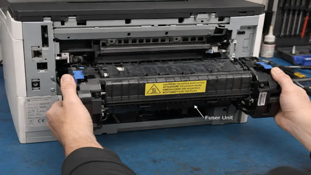
If line voltage is confirmed stable, the fault lies within the printer’s internal heating circuit. You must safely extract the fuser for bench testing.
-
Ensure the printer has been unplugged and idle for at least 45 minutes to prevent severe burns.
-
Open the rear output door of the printer.
-
Depending on your specific model, release the rear door hinges and remove the door completely to expose the fuser assembly.
-
Locate the fuser retention mechanism. Most modern HP models utilize two blue plastic locking tabs or two Phillips-head screws on the left and right flanks.
-
Disengage the tabs or remove the screws.
-
Gently pull the fuser straight out of the chassis. Avoid touching the delicate brown or gray pressure roller.
Phase 3: Multimeter Continuity and Resistance Testing
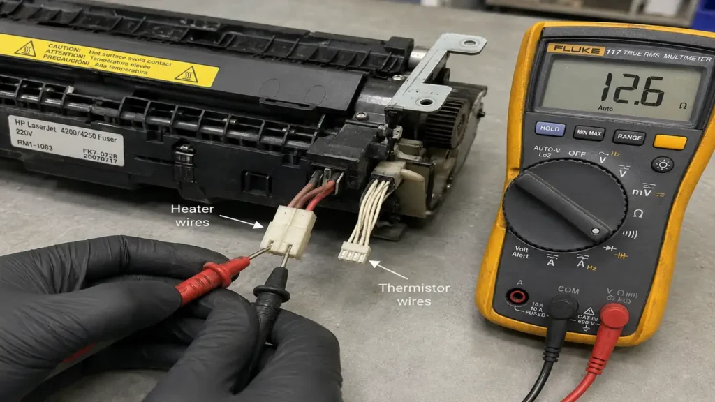
With the fuser safely on a static-free bench, you can use a digital multimeter to determine if the internal components have failed.
Testing the Ceramic Heater (AC Circuit)
The primary power connector on the fuser typically features two thick, heavy-gauge wires (often white and black). These feed AC voltage to the ceramic heater.
-
Set your multimeter to the Ohms (Ω) / Resistance setting.
-
Insert your multimeter probes into the two thick electrical contacts on the fuser’s main plug.
-
A healthy 110V/220V heating element should display a resistance reading typically between 50 Ω and 100 Ω (exact values vary by model).
-
If the multimeter displays “OL” (Open Loop) or infinite resistance, the ceramic heating element is physically cracked or blown. The fuser is permanently dead and must be replaced.
Testing the Thermistors (DC Circuit)
The secondary connector features several very thin wires. These transmit low-voltage DC signals from the temperature sensors (thermistors) back to the logic board.
-
Keep the multimeter on the Ohms (Ω) setting.
-
Probe the pins associated with the thin wires.
-
Thermistors generally exhibit very high resistance at room temperature (often measuring in the hundreds of kilo-ohms (kΩ)).
-
If you read “OL” across the thermistor pins, the sensor has blown, and the logic board is throwing the 50.4 error because it is “blind” to the fuser’s temperature.
Phase 4: Engine Control Board (ECB) Assessment
If your multimeter tests confirm that both the ceramic heater and the thermistors display healthy resistance values, the fuser itself is likely intact.
This presents a more complex diagnostic scenario. If the fuser is healthy and the wall power is stable, the printer’s internal Engine Control Board (ECB) has likely sustained damage.
Power surges can destroy the Triac component on the ECB, rendering the board incapable of sending voltage to the fuser.
In this specific outcome, replacing the fuser will not resolve the 50.4 error. The logic board or power supply assembly requires professional component-level replacement, which often exceeds the economic value of older consumer printers.