

When an error 36 mimaki plotter message halts a print-and-cut job, the machine’s optical sensor has failed to read one or more printed registration marks (crop marks). Depending on your model series and firmware, the LCD screen displays this fault as [ERR36 MARKdetect], [ERROR 36: MARK DETECT], or [ERROR c36 Mark detect]. The error does not mean the optical sensor hardware has failed permanently; in most workshops, it occurs because the registration mark parameters under the plotter’s MARK DETECT menu do not match the RIP software output, the carriage is moving too fast between copies (SPD LIMIT), or the red LED pointer was positioned outside the target detection zone.
Clearing a mimaki cutter error 36 requires verifying your physical sheet alignment and printed mark geometry first, then matching the machine’s internal mark detection settings—including point count, mark dimensions, travel speed limit, and sensor sensitivity—to your print file.
How Error 36 and Error C36 Appear Across Mimaki Models
Mimaki uses the same underlying code across standalone cutting plotters and integrated print-and-cut machines, but the exact message phrasing depends on the device family and when the read failure happens during the workflow:
-
[ERR36 MARKdetect]or[ERROR 36 MARK DETECT]: Standard on CG-SRIII series plotters (CG-60SRIII, CG-100SRIII, CG-130SRIII) and CG-FX / CG-FXII / CG-FXII Plus cutters whenever the optical sensor scans across the expected mark coordinate without detecting a valid black line edge. -
[ERROR C36 MARKdetect]or[ERROR c36 Mark detect]: Displayed on CG-AR series vinyl cutters and CJV150 / CJV300 print-and-cut systems when no registration mark is found during initial automatic or semi-automatic mark detection. -
COPY SKIPFollowed by[ERROR 36: MARK DETECT]: During continuous multi-copy cutting on models such as the CG-AR series, failing to read a registration mark on a single pattern triggers a temporaryCOPY SKIPalert and skips that single pattern. If the sensor fails to read registration marks continuously across five or more patterns, the plotter aborts the job and latches[ERROR 36: MARK DETECT].
Understanding whether the fault appears on the very first registration mark (TP1) or mid-job during continuous matrix cutting helps pinpoint whether you are dealing with an initial positioning/configuration mismatch or high-speed media slippage.
Why the Optical Sensor Fails to Read Registration Marks
Before changing sensor calibration values, identify which physical or software condition is preventing the optical sensor from recognizing the printed lines:
-
Control Panel and Software Parameter Mismatch: The registration mark form (Type 1 outer square brackets vs. Type 2 inner corners), mark leg length, or detection point count set on the plotter panel disagrees with the marks generated in FineCut (FineCut8 or FineCut/Coat9) or RasterLink.
-
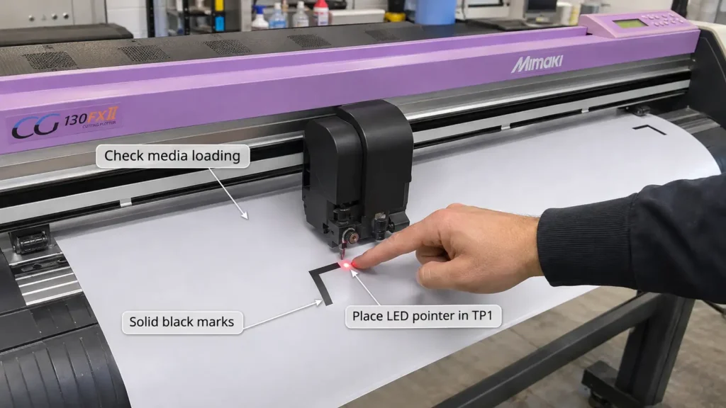
Incorrect Initial LED Pointer Placement: In manual or semi-automatic detection mode, the operator must jog the red LED light pointer directly into the designated TP1 starting area before pressing
[ENTER/HOLD]. If the pointer rests directly on top of the black ink line, outside the corner boundary, or on the wrong corner because the sheet was loaded upside down, the initial scan fails immediately. -
Media Slippage at High Travel Speeds (
SPD LIMIT): When cutting sheets with multiple repeated patterns (COPIES A/COPIES B) or dense bursts of small stickers, rapid grit-roller acceleration between patterns can cause heavy or laminated vinyl to slip slightly. By the time the carriage reaches the next set of marks, the printed corner has shifted outside the sensor’s scan window. -
Low Contrast, Laminate Glare, or Ink Defects: The optical sensor expects sharp, solid black marks printed on a clean white background. Clogged printhead nozzles that leave banding across the mark, glossy overlaminates reflecting overhead shop lights, strong light shining into the rear of the plotter, or stray ink splatters inside the unprinted margin around a mark will blind or confuse the sensor.
-
Post-Design Scaling in the RIP: If a print file containing FineCut registration marks is scaled up or down inside the RIP software before printing, both the line thickness and the mark leg length change, causing the plotter to reject the mark dimensions.
Once you know which factor applies to your job, start with physical media and mark inspections before modifying the plotter’s internal setup menu.