

Step 1: Check Media Loading, Mark Print Quality, and LED Pointer Position
Many error c36 mimaki interruptions are caused by physical setup issues at the platen rather than menu misconfigurations. Perform these baseline checks before altering firmware settings:
-
Verify Mark Size and Print-Free Margins: Confirm the registration marks are printed in solid black and measure between 4 mm and 40 mm per side (if the horizontal and vertical lines differ in length, the plotter references the shorter side). Ensure no artwork, dust, or ink smudges intrude into the white clear zone surrounding each mark.
-
Check Spacing Between Multiple Jobs: If you arranged two separate jobs next to each other on the same roll, their registration marks cannot sit too close together. For Type 1 marks, the gap between adjacent mark sets must be more than twice the mark side length (and under 1,000 mm). For Type 2 marks, the gap must be greater than one mark side length (and under 1,000 mm).
-
Eliminate Rear Glare and Media Curl: Ensure the vinyl lies completely flat across the platen with at least 20 mm of side margin outside the pinch rollers, and verify that the clamp lever is set to the appropriate pressure mode so the grit rollers grip firmly. Shield the rear of the machine if direct sunlight or bright task lighting shines toward the platen.
-
Align the LED Pointer Correctly for TP1: Reload the media and check your loading direction. Note that when loading media using the front specification rather than the rear specification, the positions of marks TP1 through TP4 are reversed. Use the Jog arrow keys to place the red LED dot inside the TP1 detection area, keeping the light spot at least 1 mm away from the black lines of the mark before pressing
[ENTER/HOLD].
If the sheet is loaded squarely and the LED pointer sits in the exact target zone but the carriage still stops with Error 36, proceed to the control panel setup menu.
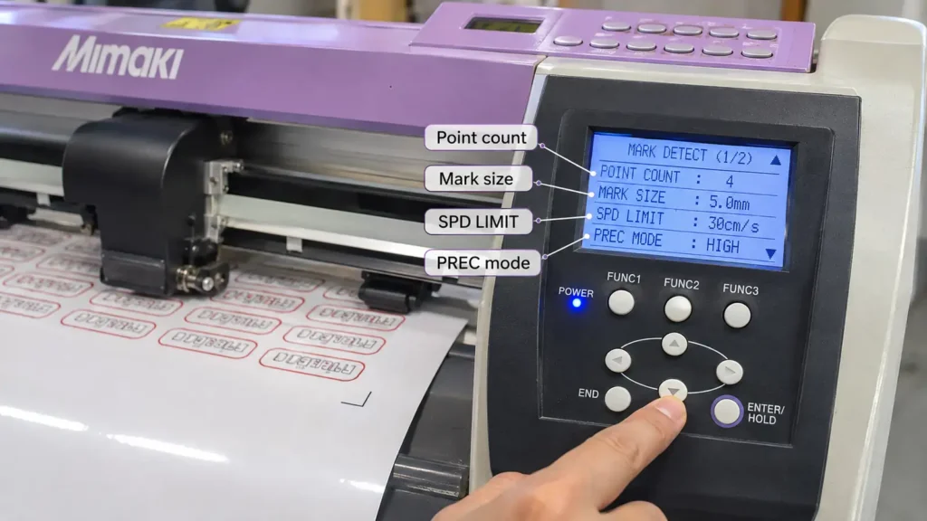
Step 2: Configure MARK DETECT and SPD LIMIT on Mimaki CG Plotters
On standalone cutters such as the Mimaki CG-130SRIII (CG-SRIII series) and CG-AR series, adjusting the registration mark detection parameters and carriage speed limit directly on the control panel resolves mismatches between the plotter and your cut data:
-
Put the plotter into Local Mode and press the
[FUNCTION]key (on the CG-130SRIII and other CG-SRIII models, this corresponds to theFUNC3softkey beneath the LCD screen). -
Use the Up/Down Jog keys to highlight
SET UPand press[ENTER](or[ENTER/HOLD]). -
Scroll through the setup list until
MARK DETECT(displayed asTP DETECT [MARK DETECT]on some firmware versions) appears, then press[ENTER]. -
Review and configure the sub-parameters inside the
MARK DETECTmenu to match your job:-
Detection Points (
1pt,2ptA,2ptB,3pt,4pt): If you are sending the cut job directly from FineCut/Coat9, set the plotter panel to1pt—Mimaki’s firmware gives precedence to the number of registration marks configured inside FineCut. If you are running standalone detection from panel settings, choose the exact point count (2ptAfor feed-direction compensation,2ptBfor width-direction compensation,3pt, or4ptfor full trapezoidal and scale compensation) that matches your layout. -
Mark Shape and Size (
SIZE): Verify that the selected mark style (Type 1 or Type 2) matches your print and setSIZE(4 to 40 mm) to the exact length of the printed mark line. -
Filled Registration Marks (
MARK FILL UP): Keep this set toOFFfor standard black marks on white vinyl. SetMARK FILL UPtoONonly when cutting colored or non-white media where you used FineCut’s “Fill around the register mark” feature to print a contrasting background box around the mark. When usingMARK FILL UP, the registration marks must be at least 10 mm in size.
-
-
Scroll to
SPD LIMIT(Speed Limit) within the mark detection settings and press[ENTER].-
The
SPD LIMITparameter accepts values from0to60 cm/s(0leaves high-speed movement unrestricted). -
When cutting small contour graphics or multi-copy sheets where heavy or slick vinyl shifts during rapid movement between patterns, lower
SPD LIMITto a controlled speed (such as 10 to 30 cm/s). Slowing the transition speed prevents media slippage so the optical sensor arrives directly over each subsequent registration mark.
-
-
Press
[ENTER]to save each parameter, then press[END]to return to Local Mode and run a test detection.
Step 3: Tune Detection Mode and Sensor Sensitivity for Laminated or Colored Media
When glossy lamination, matte textured overlaminates, or slightly faded print contrast prevent the sensor from locking onto valid marks, adjust the optical scan method and sensor gain inside the same registration mark menu:
| Parameter | Available Settings | Recommended Troubleshooting Adjustment |
DETECT MODE |
FAST (High Speed) / PREC (Precision) |
Switch from FAST (bidirectional scanning) to PREC. Precision mode takes slightly longer to scan each mark line but significantly improves edge recognition accuracy on laminated or low-contrast media. |
SENSOR LEVEL |
1 to 7 (Default: 4) |
Increase the value above 4 if the sensor fails to detect valid marks and triggers Error 36 immediately. Decrease the value below 4 if surface reflection, media grain, or dust causes the sensor to false-trigger before reaching the black line. |
For integrated Mimaki CJV150 and CJV300 printer-cutters displaying [ERROR c36 Mark detect], access these equivalent settings on the machine panel via MENU > CUTTING > REGISTER MARK DETECTION (or MENU > Cutting > TP DETECT). Confirm that every setting on that screen matches the mark configuration inside FineCut or RasterLink6 / RasterLink7.