

Step 4: Test the Mark Sensor and Calibrate Pointer Offset
If your software settings, MARK DETECT parameters, and SPD LIMIT values are all configured properly—yet the plotter still fails to find marks or cuts slightly off-register—the physical offset between the red LED pointer, the optical sensor lens, and the cutter blade may have drifted, or the sensor lens may be dusty.
Inspect and Test Sensor Responsiveness
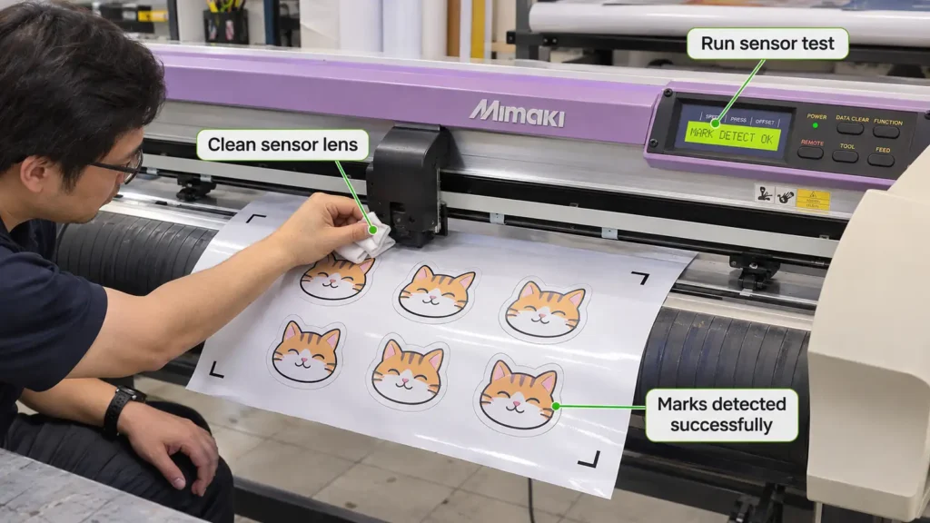
First, power off the plotter and gently wipe the underside of the optical mark sensor lens beside the carriage using a clean, dry, lint-free cotton swab to remove vinyl dust or adhesive residue.
Next, verify that the sensor is reading black-to-white transitions properly:
-
Ensure the panel key buzzer is enabled under
[FUNCTION]>SET UP>BUZZER>ON(setting the buzzer toOFFmutes the sensor test tone). -
In Local Mode, press
[FUNCTION], scroll toMARK SENSOR, and press[ENTER/HOLD]to run the built-in responsiveness check over a printed registration mark. -
Follow the on-screen automated scan prompt. Do not attempt to test sensor responsiveness by pushing the carriage or pulling the vinyl sheet by hand; manual movement cannot accurately verify optical sensor triggering.
Calibrate Light Pointer and Sensor Offset (POINTER OFFSET / SENSOR OFS)
When the red LED beam no longer matches the optical sensor’s actual focal point, the sensor misses the mark line during manual positioning:
-
On CJV150 / CJV300 Series: Navigate to
MENU>Cutting>MAINTENANCE>MARK SENSOR>POINTER OFFSETand follow the panel prompts to align the light pointer coordinate with the registration mark sensor. -
On CG-AR and CG-SRIII Series: In Local Mode, press
[FUNCTION]>MARK SENSOR>SENSOR OFSand press[ENTER/HOLD]. After confirming the media slot (MEDIA 1throughMEDIA 8), the plotter reads a single printed registration mark and cuts a center crosshair flanked by five auxiliary reference lines spaced at 0.2 mm intervals on each side. Inspect which cut line aligns dead-center with the printed mark lines, enter the corresponding A-axis and B-axis correction values (in mm) using the Jog keys, and press[ENTER/HOLD]to store the calibration in non-volatile memory.
Once calibrated, reload the vinyl sheet, position the LED pointer inside TP1, and initiate your print-and-cut job—the optical sensor will now track registration marks reliably without halting on Error 36.